ANTENNA
DESIGN
USING
THE FDTD
Created
22 Mar 2016
Updated
22 Mar 2016
INTRODUCTION
UNIVERSITY OF SHEFFIELD (UK)Dept. of Electronic and Electrical Engineering
Final Year Project, 1999
'Impulse Antenna Design Using the FDTD'
by Guillermo Luijk
Supervisor: Dr. G. Junkin
Second marker: Dr. B. Chambers
ABOUT THE FDTD CODE
The FDTD simulation FORTRAN code took 4 months to be finished starting from a previous Final Year Project by S. Iranzo [1]. I borrowed from his great work the Near zone to far zone transformation and the 2nd order Mur ABC routines. The result was a powerful FDTD program featuring:- Object-oriented approach
- Wire elements of arbitrary length, orientation and radius (sub-cell formulation)
- Perfect conductor rectangular sheets, rectangular volumes and ellipsoidal volumes
- Dielectric and resistive rectangular sheets, rectangular volumes and ellipsoidal volumes of arbitrary electromagnetic parameters
- Derivation of complex shapes from existing primitives setting priorities
- 2nd order Mur Absorbing Boundary Conditions
- Time domain near zone to far zone transformation
- Multiple configurable feed and observation points
- Top, front and side previews of the geometry under simulation
- Electromagnetic fields, voltage, current, charge density, power pattern, surface power density and SAR distributions calculations
- Wide-band input impedance, gain and far-field radiation pattern calculations through FFT
Most plots in the next sections were obtained by applying MatlabTM graphic capabilities to the output data produced by the FDTD software.
WIRE ELEMENT SIMULATIONS
These three simulations were some of the first I did to check the FDTD code. Wire elements were simulated using the Thin wire approximation explained in [2].The first picture shows a dipole radiating in free space, made from two wire elements of the same size plus a feed point in the middle location. The excitation source was a sine wave and the frequency and size of the simulation are irrelevant in this case as the only intention was to check that the algorithm performed properly.
In the second simulation the dipole turned into a monopole which consisted of a wire element over a PEC plane, being fed as close to the plane as possible. Looking at the proper reflections of the waves on the plane I had the feeling the code was working fine.
Finally the same simulation was done, eliminating in this case the wire element to compare the result with the previous simulation. The result was that expected.
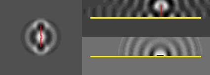
Fig. 1 Wire element simulations.
Later comparisons of input impedance results of identical EM problems obtained with well proved MoM code confirmed that the FDTD algorithm yielded good results.
MICROSTRIP SPIRAL ANTENNA
In this case a spiral microstrip antenna was simulated. The geometry was defined using hundreds of rectangular flat pieces of PEC material whose measures were obtained through a dedicated piece of software by Dr. G. Junkin which allowed to generate a complex list of rectangular pieces from any arbitrary bitmap design.The result was a very easy and effective way to implement any imaginable antenna design with very little effort. To update the electric fields for each of these rectagunlar pieces was a very quick task which did not slow down the simulation process at all.
The picture shows the electric field distribution in logarithmic scale after a gaussian pulse was used as excitation source during 2500 steps. This simulation took no longer than two hours to be finished on a Pentium 200.
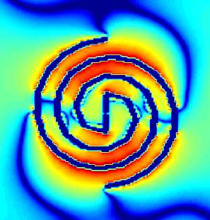
Fig. 2 Microstrip spiral antenna.
Simulation parameters:
- Max. antenna dimension: 32 mm
- nx·ny·nz = 147·130·40 cells
- dx = dy = dz = 0.32 mm
- dt = 0.6 ps (97.4% Courant limit)
- No. of steps: 2500
- Source: gaussian pulse, Zo = 50 ohm
PRINTED LOADED DIPOLE
In the same way as with the spiral antenna, we simulated a flat antenna shape dividing it in numerous smaller rectangular pieces and calculating electric fields subsequently for each of them.First we simulated only the printed dipole antenna. Its behaviour proved to be very similar to that of an ideal dipole antenna and clearly the input impedance profile obtained shows this. Also the impulse response was depicted:
Fig. 3 Input impedance and impulse response of printed dipole.
Then we 'added' two triangular pieces of resistive material providing a resistivity of 200 ohm/sq. The calculation of the new input impedance showed clearly the effect of the loading in softening both the input impedance and the impulse response.
More impressive however is the electric field distribution which is showed here in logarithmic scale:
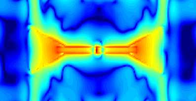
Fig. 4 Printed loaded dipole E field.
Finally the charge distribution over the same antenna is shown where green colour means positive, and red colour means negative charge:
Fig. 5 Printed loaded dipole charge distribution.
Simulation parameters:
- Antenna dimensions: 26x9 cm
- nx·ny·nz = 190·100·40 cells
- dx = dy = dz = 2 mm
- dt = 3.84 ps (99.7% Courant limit)
- No. of steps: 500
- Source: gaussian pulse, Zo = 50 ohm
IMPULSE ANTENNA
In this simulation we tried to analyze the impulse response of a prototype of the impulse antenna design by British Gas showed here: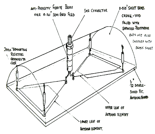
Fig. 6 Impulse antenna prototype by British Gas.
However a rectangular geometry was chosen instead, in order not to make the problem too complicated.
Unfortunately the pulse width was not chosen adequately and multiple reflections inside the case produced a far from desired impulse response. Also filling the box with a dense dielectric like in the original design would have been necessary to atenuate wave propagation.
The following picture shows the preview provided by the simulation program to ease antenna geometry checking, and mousing over the instantaneous electric field:
Fig. 7 Three views of antenna design and electric field propagation (mouse over).
Simulation parameters:
- Antenna dimensions: 18x8x6 cm
- nx·ny·nz = 150·100·80 cells
- dx = dy = dz = 2 mm
- dt = 3.84 ps (99.7% Courant limit)
- No. of steps: 2000
- Source: gaussian pulse, Zo = 50 ohm
MOBILE PHONE
Now we will simulate a mobile phone handset together with a phantom human head modelled through an ellipsoid of constant electromagnetic parameters.Firstly we calculated the far-field radiation patterns of the group handset+head for two usual frequencies. To do this we made use of the Near zone to far zone transformation presented in [3].
Looking at the logarithmic polar plots obtained, we conclude that the effect of the head (the position of which is shown in dotted line) is evident but not determinant in the radiation patterns:
Fig. 8 Mobile phone + human head radiation patterns.
Noticeabe is the magnitude of the phi component of the electric field, which is typical in practical mobile communications systems producing a non linear polarisation in the far field.
Also the instantaneous electric field magnitude was graphed. With a fantasy colour map, the propagation of the radiowaves through the phantom head can be apreciated. In those points close to the boundaries where the wave propagation direction is almost parallel to the boundary, the Mur 2nd order ABC reveal not to be very precise:
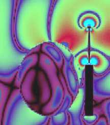
Fig. 9 E field propagation from mobile phone.
The last picture shows the SAR distribution over the phantom head caused by the mobile phone radiation. A CW signal was used to perform this calculation and no absolute values were obtained as the simulation was done just for testing purposes.
Rarely, SAR power values calculated on the right side of the head had a greater magnitude some cm inside the head than in those points closer to the head's surface and therefore closer to the radiation source:
Fig. 10 SAR distribution over human head model.
Simulation parameters:
- Antenna dimensions: Rob's head?
- nx·ny·nz = 100·100·110 cells
- dx = dy = dz = 2.5 mm
- dt = 4.8 ps (99.7% Courant limit)
- No. of steps: 900
- Source: gaussian pulse and CW, Zo = 0 ohm
INDOOR PICOCELL
In the last place, and although simulating radio propagation in large structures such as buildings is not a stronghold of FDTD as phase errors become important when the simulated structures are large when compared to the wavelength, several studies have appeared showing modified time-stepping update schemes to reduce phase errors in these situations. A good example of this can be found in [3].In this case we have used our standard FDTD code just to show an hypothetic use FDTD can be given in radio coverage and building penetration simulations.
The antenna used was a dipole of about 50 cm long located in one of the rooms inside the building, and different electromagnetic parameters were taken into account to define the different elements under simulation (walls, doors, windows,...). A test path inside the building was defined in order to calculate the power profile:
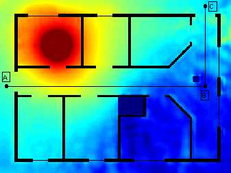
Fig. 11 Indoor wave propagation and walking path.
Here the relative power profile along the path is shown. Ringing caused by multiple signal contributions due to reflections on the walls is clearly seen.
Fig. 12 Signal level received along walking path.
Simulation parameters:
- Building dimensions: 18x13 m
- nx·ny·nz = 200·150·50 cells
- dx = dy = dz = 10 cm
- dt = 0.19 ns (98.7% Courant limit)
- No. of steps: 690
- Source: CW at 27 MHz, Zo = 0 ohm
REFERENCES
[1] S. Iranzo, "A finite-difference time-domain program for analysis of ground probing radar strategies," Final Year Project, The University of Sheffield, Dept. of Electronic and Electrical Eng., 1995.[2] K. R. Umashankar et al., "Calculation and experimental validation of induced currents on coupled wires in an arbitrary shaped cavity," IEEE Trans. Antennas Propagat., vol. AP-35, pp. 1248-1257, November 1987.
[3] M. F. Hadi and M. Piket-May, "A modified FDTD (2,4) scheme for modelling electrically large structures with high phase accuracy," IEEE Trans. Antennas Propagat., vol. AP-45, pp. 254-264, February 1997.
If this content has been useful to you, please consider making a contribution to support this site. Keeping it means an important effort, so as considerable storage space and bandwidth in the server. It is a simple and totally secure operation.
gluijk@hotmail.com